


 127 / 287

[
] 128
O
bserving
, P
redicting
and
P
rojecting
C
limate
C
onditions
vation orbit and swath design are crucial for the sensor system to
work. A sun-synchronous orbit with an approximate height of 800
kilometres and a 34 day revisit period was selected. Considering
the observation frequency requirement, the sensor swath should be
wider than 1,100 kilometres for every two-day observation at mid-
latitude. Because we are using a push-bloom type sensor for VNR,
swath is an important parameter. The detector array size and total
volume of optics depends largely on this parameter. The preferred
local time at descending node is 10.30, taking into account the
amount of cloud over the land.
VNR consists of a non-polarimetry part, a polarimetry part, an
on-board calibrator and an electrical component. For the non-
polarimetry part, which has 11 channels, there are three telescopes
to cover a wide swath. To separate channels, we decided not to use
a dichroic filter to minimise polarization sensitivities by optics. So,
instead of using filters we decided to use along-track direction for
spectral channels, though it has some parallax. Keeping a low inci-
dent angle in optical design, this sensor has very low
polarization sensitivities – lower than two per cent.
For the polarimetry part, which has two channels,
two telescopes with two wavelengths were employed.
Because the polarimetry part is designed for tilt obser-
vation, the swath can be covered with one telescope.
Two telescopes are used to minimize parallax between
the three polarization direction sub-channels, and
in each telescope there are three polarization direc-
tion sub-channels. With three polarization direction
observations at 0, 60 and 120 degrees, it is possible to
determine storks vectors (I, O, U) of observed light,
where element V of the storks vector is negligible in
natural light. Tilt observation geometry is required for
the poralimetry part. The signal from aerosol is optimal
in a forward scattering direction, therefore the observa-
tion direction must be forward tilted in the northern
hemisphere, and backward tilted in the southern. In
one orbit, the sensor tilts forwards and backwards once
each. The scatter angle of aerosols to be measured is
between 60 and 120 degrees.
For both non-polarimetry and polarimetry about
6,000 element CCDs were used to cover a 1,150 kilo-
metre swath. To divide channels spectrally there is a
striped colour filter on each detector array. For polar-
imetry, a striped polarizer is added. Then, the observed
signal is digitized with a 12bit analogue-to-digital
converter. When the satellite is not over land or coastal
areas, the 250-metre resolution data will be integrated
and averaged on board into 1-kilometre resolution data.
The daily total data download rate will be about 70 giga-
byte, including both VNR and IRS data.
For on-board calibration, the satellite is equipped
with a solar diffuser, as well as an internal light. An
attempt will also be made to use the Moon as a stable
natural light source. Other observation modes for cali-
Centre
frequency
[GHz]
6.925 / 7.3
10.65
18.7
23.8
36.5
89.0
Band width
[MHz]
350
100
200
400
1000
3000
Polarization
V and H
Beam width
[deg.] (Ground
resolution [km])
1.8 (35 x 62)
1.2 (24 x 42)
0.65 (14 x 22)
0.75 (15 x 26)
0.35 (7 x 12)
0.15 (3 x 5)
Sampling
interval
[km]
10
5
Frequency channels and resolutions of AMSR2
Source: JAXA
Channel
Centre
Band Standard Maximum Ground
wavelength width Radiance Radiance resolution
VN,P,SW: nm VN, P: W/m
2
/sr/µm m
T: µm T: Kelvin
VN1
380
10
60
210
250
VN2
412
10
75
250
250
VN3
443
10
64
400
250
VN4
490
10
53
120
250
VN5
530
20
41
350
250
VN6
565
20
33
90
250
VN7
673.5
20
23
62
250
VN8
673.5
20
25
210
250
VN9
763
12
40
350
1000
VN10
868.5
20
8
30
250
VN11
868.5
20
30
300
250
P1
*1
673.5
20
25
250
1000
P2
*1
868.5
20
30
300
1000
SW1
1050
20
57
248
1000
SW2
1380
20
8
103
1000
SW3
1630
200
3
50
250
SW4
2210
50
1.9
20
1000
T1
10.8
0.74
300
180~340 500
T2
12.0
0.74
300
180~340 500
SGLI channel specifications
Source: JAXA
*1
Polarization channels should have capability to observe at three polarization
direction (0,60,120 deg.) and NADIR / Tilt view at +-45 deg
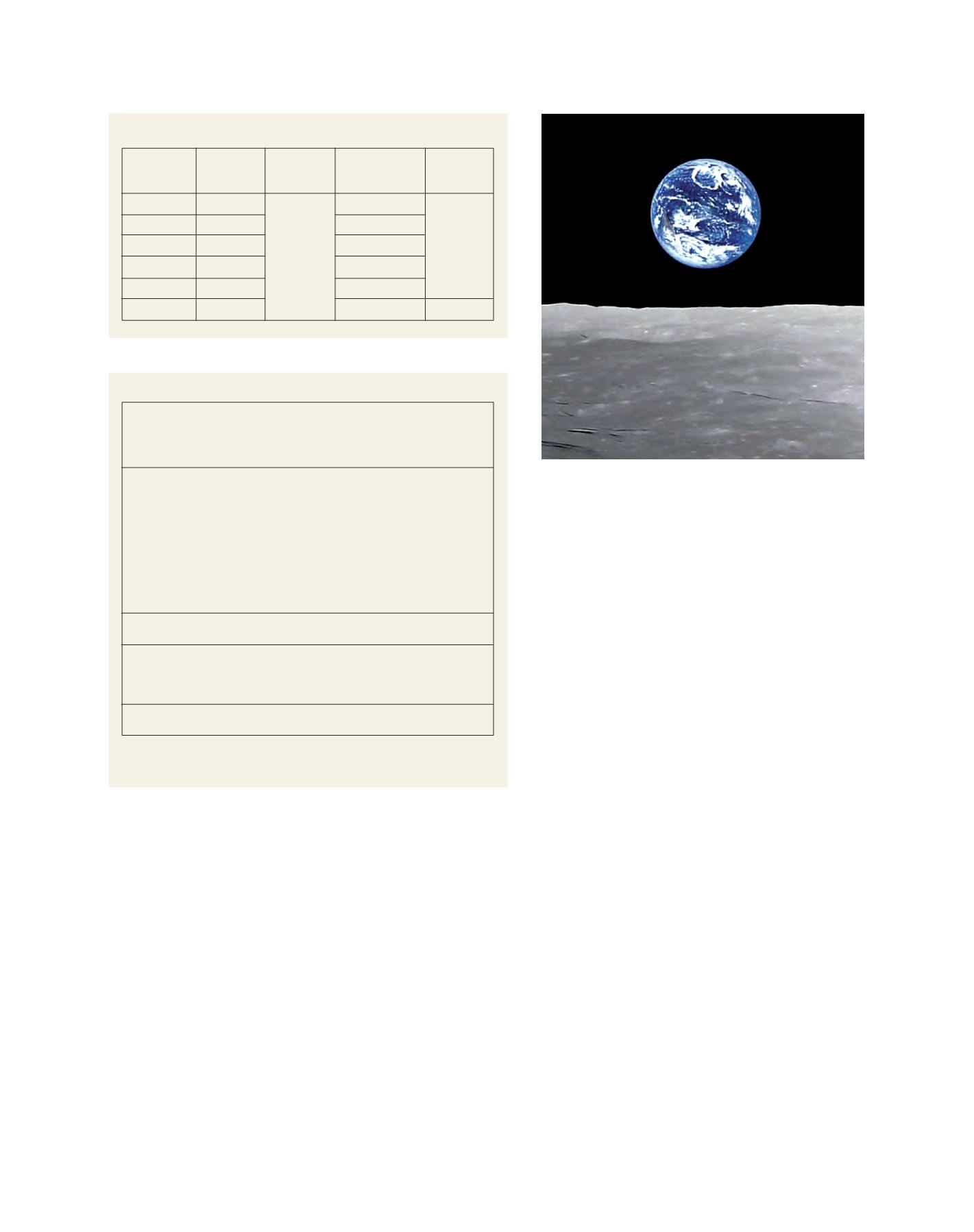
“Full Earth-rise” taken by HDTV on JAXA’s Kaguya (SELENE) Spacecraft
Image: JJAXA/NHK